
This document describes the default values, communication speed, controller station number, control area/status area, controller wiring instructions, controller Read/Write address definition and other contents of Allen-Bradley SLC5 HMI.
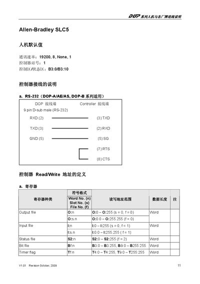
This manual provides detailed information on the SLC5 controller, including its RS‑232 communication interface, register organization, and file structures. It lists the baud rate, connector type, and pin assignments for serial connections.
The document also defines the symbol format for various file types such as Output, Input, Status, Timer, Counter, Control, Integer, Floating‑point, String, and Long Word files, showing the slot, file and bit numbering used in programming the PLC. This manual is written in Japanese.
| RS‑232 baud rate | 19200, 8, None, 1 |
|---|---|
| RS‑232 connector | 9‑pin D‑sub male |
The RS‑232 connection uses a baud rate of 19200 with 8 data bits, no parity, and 1 stop bit.
It uses a 9‑pin D‑sub male connector for RS‑232.