
CD22M3494EVM user manual, introduces how to use CD22M3494EVM evaluation board, including evaluation board appearance, power on method, use method, component list, etc.
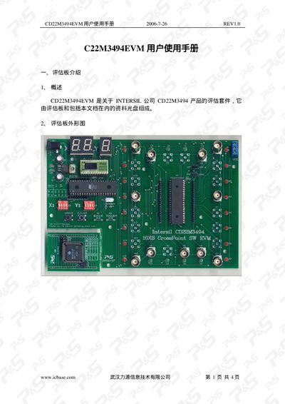
This manual introduces the CD22M3494EVM evaluation board, which is a fully assembled test platform for the Intersil CD22M3494 chip. It describes the board’s physical layout, required power connections, and the purpose of each connector and jumper.
The guide details the power‑on procedure, how to select internal or external supplies with JP1, the meaning of the LED indicators, operation of the DIP switches and buttons (UPDATE and CLR/RST), and provides a complete component list, basic electrical parameters, and the schematic diagram. This manual is written in Chinese.
| Supply Voltage | 9 V DC |
|---|---|
| Maximum Supply Current | 500 mA |
| Operating Temperature | 0 °C to 70 °C |
| Relative Humidity | 0 % to 95 % (non‑condensing) |
Connect a 9 V DC supply to the J1 connector; the LED indicators will light when power is applied.
The segment LED at the top left displays the X and Y channel settings, while the side LEDs indicate whether each channel is on (flashing) or off (steady).