
The LTC ®1066-1 is an 8th order elliptic lowpass filter which simultaneously provides clock-tunability and DC accuracy. The unique and proprietary architecture of the filter allows 14 bits of DC gain linearity and a maximum of 1.5mV DC offset. An external RC network is used to set the filter's cutoff frequency and phase. The device has high output swing, capable of driving a 1kΩ load, and features 0.02% THD or better distortion.
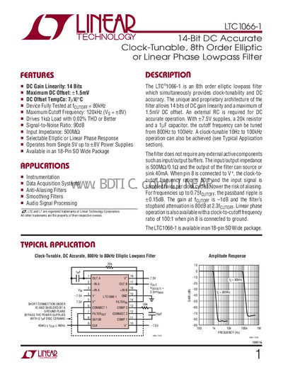
The LTC1066-1 provides a high‑performance low‑pass filter solution with both elliptic and linear‑phase options. It offers 14‑bit DC gain linearity, a maximum DC offset of 1.5 mV, and can be clock‑tuned from 800 Hz to 80 kHz. The device operates from a single 5 V supply up to +8 V and is available in an 18‑lead SO wide package.
The datasheet includes detailed electrical characteristics, pin functions, typical performance graphs, and recommended application circuits. It also specifies absolute maximum ratings, package dimensions, and ordering information for both standard and lead‑free versions.
| DC Gain Linearity | 14 Bits |
|---|---|
| Maximum DC Offset | +1.5 mV |
| Input Impedance | 500 MΩ |
| Power Supply Range | +2.375 V to +8 V |
| Output Short‑Circuit Current | +20 mA |
The filter can operate from a single 5 V supply up to +8 V, with low‑noise linear supplies preferred; switching supplies are not recommended.
Connecting pin 8 to V* sets a 50:1 ratio for elliptic response; connecting pin 8 to ground (or ½ V) sets a 100:1 ratio for linear‑phase response.
A 30 kΩ resistor in series with a 15 pF capacitor between pins 11 and 13 is recommended for certain temperature and frequency conditions.