
OPTIDRIVE P2 variable speed drive encoder interface modules user guide, introduces the modules function features, usage methods, installation instructions and so on
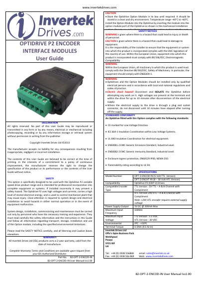
This Invertek Drives User Guide covers the OPTIDRIVE P2 Encoder Interface Modules, model OPT-2-ENCOD-IN (5 Volt TTL version) and OPT-2-ENCHT-IN (8-30 Volt HTL version), for use with Optidrive P2 (ODP-2) drives. It documents safety notices, standards conformity, specifications, mechanical installation, connection terminals, LED status indication, parameter settings, commissioning and error code definitions.
Safety information stresses that installation, commissioning and maintenance must be carried out only by trained personnel, that the drive must be isolated before work, and that high voltages remain for up to 10 minutes after disconnection. The guide also lists a 2-year warranty from the date of manufacture.
| Model Number | OPT-2-ENCOD-IN (5 Volt TTL Version); OPT-2-ENCHT-IN (8-30 Volt HTL Version) |
|---|---|
| Compatibility | Optidrive P2 (ODP-2) Drives |
| Compatible Encoder Type | TTL: 5V TTL A & B channel with compliment; HTL: 24V HTL A & B channel with compliment |
| Power Supply Output | 5V DC @ 200mA Max |
| Maximum Input Frequency | 500kHz |
| Maximum Input Voltage | TTL: 5.5 VDC; HTL: 30 VDC |
| Environmental | 0ºC - +50ºC |
| Terminal Torque | 0.5Nm (4.5 lb-in) |
| Storage Temperature | -40ºC to +60ºC |
It is designed for use with Optidrive P2 (ODP-2) drives.
As a minimum, P1-09 motor rated frequency, P1-10 motor rated speed and P6-06 encoder PPR value.
LED B (red) indicates a wiring fault condition.
The speed feedback is inverted; reverse the A and B signal channels from the encoder.