
Victron Energy Color Control GX User Manual

This manual introduces the installation and use of Color Control GX

Victron Energy Color Control GX User Manual - cover page
Brand
Victron energy
Category
Other
Document type
User Manual
Language
English
Pages
19
File format
PDF
File size
763 KB
Published
26 October, 2023
Updated
26 October, 2023
MD5 checksum
9F6369A7AD8A6BCE2FCF7E95B166C087

About this manual

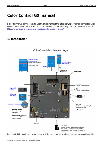
This manual provides step-by-step instructions for installing and connecting the Victron Energy Color Control GX. It covers powering the device, connecting VE.Bus products, VE.Direct devices, VE.Can devices, and NMEA2000 tank senders. Special notes address compatibility with VE.Bus BMS, deadlock prevention, and limitations when combining with other controls. The document also explains how to measure PV inverter output for display purposes only.

What's inside

  • Installation
  • Power
  • Connecting Victron products
  • VE.Bus products
  • VE.Direct products
  • VE.Can products
  • NMEA2000 tank senders
  • Measuring PV Inverter output

Frequently asked questions

What voltage range can the Color Control GX accept for power?

The device accepts 8 to 70 V DC on the Power IN V+ connector.

What type of fuse is required for the Color Control GX power supply?

You must use a 1A slow blow fuse for the power connection.

How long can the VE.Direct cables be for connecting BMVs or MPPTs?

VE.Direct cables have a maximum length of 10 meters and cannot be extended.

Download PDF (763 KB)

More Victron energy Manuals


View all Victron energy manuals →