
This manual provides detailed information on the connection methods and electrical system information for electrical systems installed in automobiles. This manual covers all models and includes bus systems, body systems, powertrain systems, steering systems, braking systems, lighting systems, air conditioning systems, audio systems, body control modules, safety airbag systems, on-board information systems, electrical systems, anti-theft systems, terminals and connectors. This manual also includes methods for diagnosing and repairing electrical systems.
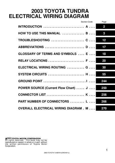
The Electrical Wiring Diagram Manual explains the vehicle’s electrical circuits, showing each system from the battery power source to ground points. It includes a full connector list, relay locations, wiring routing, and an overall wiring diagram at the end of the book.
The guide also offers troubleshooting steps, voltage reference values, and service hints to help identify faults. Symbols, abbreviations, and wire‑color codes are defined, and each part’s location is indexed for quick reference.
| Stop Light Switch voltage (on) | Approx. 12 volts |
|---|---|
| Light Failure Sensor voltage (ignition on) | Approx. 12 volts |
The Light Failure Sensor will read approximately 12 volts when the stop light switch is on.
Wire colors are shown with an alphabetical code, such as B = Black, W = White, BR = Brown, L = Blue, etc.
The overall wiring diagram is located at the end of the manual.
The first letter "E" indicates the component is located in the Engine Compartment.