
This file is the EA42-7 generator automatic voltage regulator operating manual, which details the product's functions, characteristics, usage methods, installation and maintenance
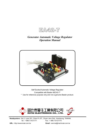
This manual provides step-by-step instructions for installing, wiring, and operating the Kutai EA42-7 automatic voltage regulator. It includes details on power and sensing input connections, frequency compensation, over-excitation shutdown, and field flashing procedures. The regulator is compatible with 50/60 Hz systems and supports voltage adjustment via internal or external rheostats. It also covers troubleshooting steps for voltage regulation issues and field build-up problems.
The manual includes diagrams for wiring and mounting, along with safety notes and precautions for handling the device and its connections.
| Input Voltage | 200 ~ 260 VAC ± 10%, 1 phase |
|---|---|
| Output Voltage | Max. 42 VDC |
| Continuous Current | 7A |
| Voltage Regulation | < ± 1% (with 4% engine governing) |
| Voltage Build-up | Residual voltage at AVR terminal > 5 VAC |
| Dimensions | 140mm L * 125mm W * 79.4mm H |
| Weight | 680g ± 2% |
| Thermal Drift | 0.05% per °C change in AVR ambient |
| EMI Suppression | Internal electromagnetic interference filtering |
| Power Dissipation | Max. 20 watt |
Voltage regulation is less than ±1% with 4% engine governing.
Disconnect the field wires, apply a DC source (3~12 Vdc) with a current-limiting resistor, wait 3 seconds, then reconnect and restart the prime mover.