
This manual covers installation, operation, maintenance and troubleshooting for the ATS-385 Automatic Transfer Switch Control Unit.
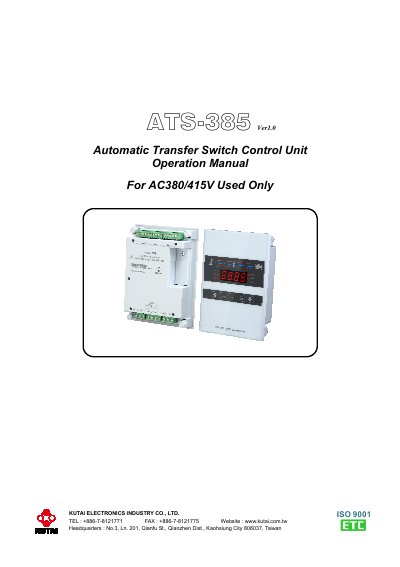
The ATS-385 is a programmable logic controller for automatic transfer switches, designed to monitor and manage power between normal and standby sources. It features a user-friendly front panel with LED indicators and membrane buttons for operation and programming. The unit supports automatic transfer, scheduled testing, and remote communication via USB, RS485, Ethernet, or Wi-Fi. It includes safety features like voltage and frequency monitoring, and programmable time delays for engine start, cool-down, and transfer operations.
Installation and operation are detailed in sections covering the operator panel, modes (AUTO, OFF, TEST), programming, and wiring. The controller is compatible with most ATS switches and retains settings in non-volatile memory even during power loss.
| Voltage Range | AC380/415V |
|---|---|
| Time Delay Emergency to Normal | 00 − 999 sec |
| Time Delay Normal to Emergency | 00 − 250 sec |
| Over Voltage Adjustment Range | 390 − 490 Vac |
| Under Voltage Adjustment Range | 300 − 410 Vac |
| Over Frequency Adjustment Range | 51 − 75 Hz |
| Under Frequency Adjustment Range | 40 − 59 Hz |
The ATS-385 is designed for AC380/415V systems.
The controller can maintain the clock for up to a week without power.
The ATS-385 supports USB, RS485, Ethernet, and Wi-Fi modules for remote monitoring and control.
Press the OFF button twice to test all panel LEDs.