
This is a user guide for the AD9653/AD9253/AD9633 evaluation boards.
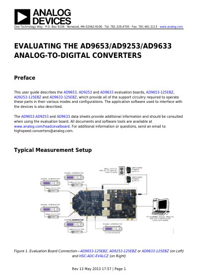
This user guide provides instructions for using the AD9653-125EBZ, AD9253-125EBZ, and AD9633-125EBZ evaluation boards. It details the required equipment, including signal generators and power supplies, and explains how to connect these components to a PC running VisualAnalog software.
The document covers hardware configuration steps such as setting jumpers for SPI communication, clocking options (internal oscillator or external source), and reference voltage selection. It also describes default circuitry settings for analog input, bias current, and power-down modes.
| Analog Input Frequency (Default) | ~200 MHz |
|---|---|
| Power Supply Voltage | 6 V, 2.5 A |
| Reference Voltage Range (AD9653) | 1.0 V to 1.3 V |
| Reference Voltage (AD9253/AD9633) | 1.0 V |
| Clock Input Amplitude | ~2.8 V p-p or 13 dBm sine wave |
Set jumper J302 by connecting Pin 1 to Pin 2 for SDIO, Pin 4 to Pin 5 for SCLK, and Pin 8 to Pin 9 for CSB.
The default setup supports analog input frequencies of up to approximately 200 MHz.
The specified reference voltage for both the AD9253 and AD9633 is exactly 1.0 V.