
This document is the user manual for the DC3064A circuit board, which uses the LTM4650A-1 chip and has high efficiency, high density, dual 25A, switch mode step-down power μModule regulator. The input voltage range is 4.5V to 16V, the output voltage can be jumper selected from 1.0V to 5.1V, and the maximum output current is 200A.
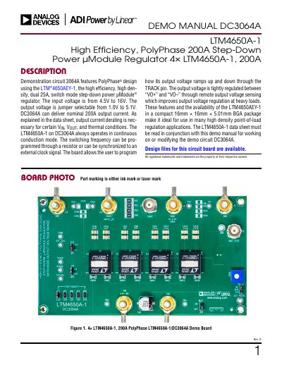
The document provides a user guide for the DC3064A demo board, which features four LTM4650A-1 regulators to deliver up to 200A of output current. The board supports input voltages from 4.5V to 16V and allows the output voltage to be jumper-selected between 1.0V and 5.1V.
| Input Voltage Range | 4.5V to 16V |
|---|---|
| Default Operating Frequency | 780 kHz |
| Resistor Programmable Frequency Range | 400 to 780 kHz |
| External Clock SYNC Frequency Range | 400 to 780 kHz |
| Efficiency (Typical) | 95.2% |
| Load Transient (Typical) | <175 mV |
The output voltage is jumper selectable from 1.0V to 5.1V.
It is recommended to split the load current evenly between J2/J4 and J13/J14.
The efficiency is 95.2% when Vin = 12V, Vout = 5.1V, Iout = 200A, and fsyw = 780kHz.