
This document is a guide for the MCU AC781x Motor Demo Board, which provides information about the board's features, interface description, and supported motor types.
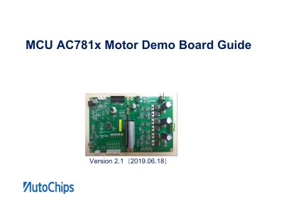
The Autochips AC781x Motor Demo Board is a development tool designed for testing and debugging Brushless Direct Current (BLDC) and Permanent Magnet Synchronous Motor (PMSM) applications. The board consists of two main sections: an MCU control board and a power drive board, connected via a 34-pin IDC cable. The MCU control board provides debugging interfaces (JTAG), communication ports (CAN, LIN, UART, SPI), and inputs for motor sensors (Hall effect and encoders). The power drive board handles the motor drive signals and power supply, supporting input voltages from 12V to 48V.
| Power Supply Input Range | 12V~48V |
|---|---|
| Connection Interface | 34-PIN IDC |
| Supported Motor Types | BLDC and PMSM |
The board supports development and debugging of BLDC (Brushless Direct Current Motor) and PMSM (Permanent Magnet Synchronous Motor).
Drive modes are selected using three jumpers: JP1, JP2, and JP3, which configure GPIO levels for Hall sensor presence and control algorithm selection.