
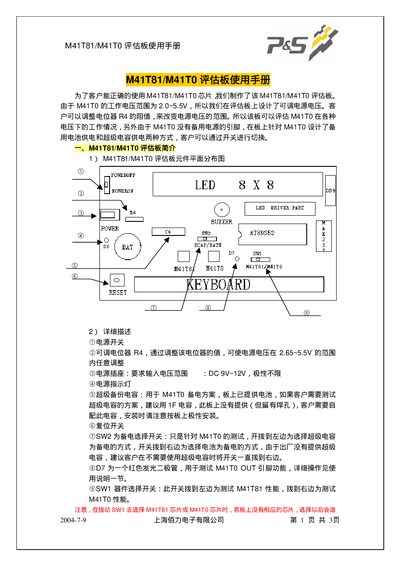
The M41T81/M41T0 evaluation board provides a platform for testing the M41T81 and M41T0 chips. It includes power input, a reset pin, several switches (SW1, SW2) and an LED matrix for status display. The board can be powered from DC 9‑12 V and operates with a supply voltage between 2.65 V and 5.5 V.
The manual describes how to navigate the on‑board menu using MENU, SELECT, INC, DEC, ENTER and CLR keys, configure time and date, output square‑wave signals at selectable frequencies, and adjust calibration offsets. It also lists the required components such as a CR2032 battery and optional 1 F capacitor for extended operation. This manual is written in Chinese.
| Input Voltage | DC 9 V‑12 V |
|---|---|
| Operating Voltage | DC +2.65 V to 5.5 V |
| Battery | Lithium CR2032 |
| Optional Capacitor | 1 F (user‑supplied) |
| SW1 Function | Selects M41T81 or M41T0 chip |
The board accepts a DC input voltage of 9 V to 12 V.
Press SELECT, then choose the desired frequency option (e.g., 8.192 kHz, 1.024 kHz, 128 Hz, 1 Hz).
SW2 selects which chip (M41T81 or M41T0) is connected to the board for testing.