
ST ANT1-M24LR16E 45 mm x 75 mm antenna reference board for the M24LR16E-R Dual Interface EEPROM handbook

This data brief introduces the features of the ANT1-M24LR16E antenna reference board, including a 45 mm x 75 mm 13.56 MHz inductive antenna, an M24LR16E-R dual interface EEPROM, an I2C connector, an energy harvesting output (VOUT) and an RF WIP/BUSY output.
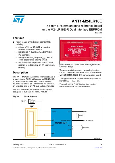

ST ANT1-M24LR16E 45 mm x 75 mm antenna reference board for the M24LR16E-R Dual Interface EEPROM handbook - cover page
Brand
STMicroelectronics
Category
Other Electronics
Document type
Product Leaflet
Language
English
Pages
4
File format
PDF
File size
141 KB
Published
07 August, 2012
Updated
30 September, 2023
MD5 checksum
D0490C1A5B06B421D083547C6AC4EF0E

About this manual

The ANT1-M24LR16E is a ready-to-use printed circuit board (PCB) designed for the M24LR16E-R Dual Interface EEPROM. It includes an etched 45 mm x 75 mm 13.56 MHz inductive antenna on one side and connects to an I²C bus on the other, allowing system designers to evaluate the chip's performance.

What's inside

  • Features
  • Description
  • Associated firmware and PC software
  • Revision history

Frequently asked questions

What is the physical size of the ANT1-M24LR16E antenna reference board?

The board measures 45 mm x 75 mm.

What frequency does the etched antenna on the PCB operate at?

The antenna operates at 13.56 MHz.

What capacitance value is used in the energy harvesting output filtering circuit?

The circuit uses a 10 nF capacitance.

Download PDF (141 KB)

More STMicroelectronics Manuals


View all STMicroelectronics manuals →