
ROBOT-M24LR16E-A is an evaluation board from STMicroelectronics which features an M24LR16E-R dual interface EEPROM IC and a 20 mm x 40 mm 13.56 MHz etched RF antenna. The board can power an external application via the VOUT pin, or the onboard LED via the LED pin.
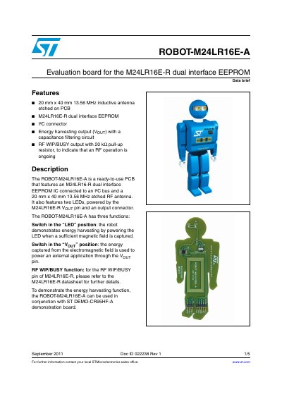
The ROBOT-M24LR16E-A is a ready-to-use PCB evaluation board designed for the M24LR16E-R dual interface EEPROM. It features a 20mm x 40mm 13.56 MHz inductive antenna etched directly onto the PCB, along with an I2C connector and an output connector for external applications.
The board supports three primary functions controlled by a switch: demonstrating energy harvesting by powering an internal LED, powering an external application via the Vout pin, and providing an RF WIP/BUSY output to indicate ongoing RF operations. It is intended for use with the ST DEMO-CR95HF-A demonstration board.
| Antenna size | 20mm x 40mm |
|---|---|
| Antenna frequency | 13.56 MHz |
| Integrated IC | M24LR16E-R dual interface EEPROM |
| RF WIP/BUSY pull-up | 20 kΩ |
The ROBOT-M24LR16E-A can be used in conjunction with the ST DEMO-CR95HF-A demonstration board.
The board features a 20 mm x 40 mm etched RF antenna.
The antenna operates at a frequency of 13.56 MHz.
The RF WIP/BUSY output includes a 20 kΩ pull-up resistor.