
This document introduces the STM32 microcontroller system memory boot mode. It describes that the main task of the bootloader stored in the internal boot ROM memory is to download the application program to the internal Flash memory through one of the available serial peripherals (USART, CAN, USB, etc.). A communication protocol is defined for each serial interface, with a compatible command set and sequences.
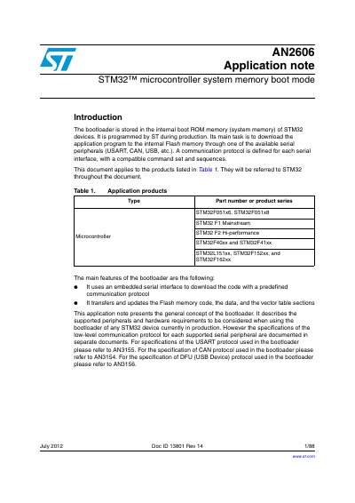
The document details the system memory boot mode used in STM32 devices, where a bootloader stored in internal ROM downloads application programs to Flash via serial peripherals like USART, CAN, or USB. It covers the general features of this bootloader and refers users to separate documents for specific low-level communication protocols.
The note provides comprehensive guidance on configuring and selecting the bootloader for multiple STM32 product lines, including Value Line (F10x), Connectivity Line (F105/107), High-Performance (F4/F2), and Ultra-Low Power (L1) series. It includes specific sections on hardware requirements, version identification, timing characteristics, and device-dependent parameters.
| Supported Serial Interfaces | USART, CAN, USB |
|---|---|
| Memory Transfer Capabilities | Flash memory code, data, and vector table sections |
The document applies to products listed in Table 1, including STM32F051x6/8, F1 Mainstream, F2 Hi-performance, L151xx/F152xx/F162xx.
Specifications for the USART protocol are documented in separate application note AN3155.
Specifications for the CAN protocol are documented in separate application note AN3154.
Specifications for the DFU protocol are documented in separate application note AN3156.