
By integrating a battery and power switching circuitry in its ZEROPOWER memory devices, STMicroelectronics was the first to develop non-volatile CMOS Static RAM technology. This is conventional, high speed, low power, random access, read/write memory that retains its data even when the external power is removed. By further integrating a crystal oscillator and a real time clock in the package for its TIMEKEEPER products, STMicroelectronics provides, in a single chip package, non-volatile SRAM and timekeeping that continues to run without external power. STMicroelectronics has subsequently extended the technique to work with surface mount packaging, in a product range that is known as the SNAPHAT.
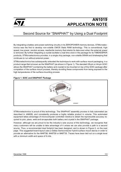
STMicroelectronics developed non-volatile CMOS Static RAM technology integrating battery and power switching circuitry in its ZEROPOWER memory devices. This technology was extended to surface mount packaging known as SNAPHAT, which allows the battery and crystal to be mounted on top of the SOIC package after the surface-mount process is completed.
The document provides a recommended dual footprint design for customers seeking an alternative source for STMicroelectronics M48T58, M48T59, or M48T35 devices. This suggested board layout utilizes a Dallas Semiconductor hybrid surface mount device to provide compatibility.
A Dallas Semiconductor hybrid surface mount device can be used as an alternative.
The traces have a minimum width and space of 6 mils.