
AD2S1200/AD2S1205 User Guide, introduces the features and characteristics of AD2S1200/AD2S1205 resolver-to-digital converters, including full-featured evaluation board, on-board excitation buffer, on-board power supplies, standalone capability, PC control and PC software control and data analysis
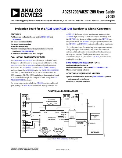
The document provides a comprehensive overview of the EVAL-AD2S1200/05SDZ evaluation board for the AD2S1200 and AD2S1205 resolver-to-digital converters. It details the on-board components, including power supplies, excitation buffers, and various analog and digital chips like the AD8664 op amp and ADM1185 voltage monitor.
The guide includes a quickstart section for setting up the hardware with the EVAL-SDP-CB1Z system demonstration platform and installing the accompanying PC software. It also covers hardware link options, power supply requirements, interface configurations (parallel/serial), and fault detection features.
| Resolution | 12-bit |
|---|---|
| Interface Types | 12-bit parallel port or 3-wire serial interface |
| Input Voltage Range | 9 V ± 5% |
| Analog Supply Rail | 5 V ± 5% |
| Digital Supply Rail | 5 V ± 5% |
| Excitation Buffer Supply | 9 V to 15 V |
The System demonstration platform (EVAL-SDP-CB1Z) is required when using the evaluation software.
The default setup configures the board to operate with the mains power supply adapter and interface via the parallel interface.
When the RDVEL link option (LK3) is in Position D, the RDVEL signal is tied to DGND.