
The UCC1913 family of negative voltage circuit breakers provides complete power management, hot swap, and fault handling capability. The IC is referenced to the negative input voltage and is driven through an external resistor connected to ground, which is essentially a current drive as opposed to the traditional voltage drive. The on-board 10V shunt regulator protects the IC from excess voltage and serves as a reference for programming the maximum allowable output sourcing current during a fault. All control and housekeeping functions are integrated, and externally programmable. These include the fault current level, maximum output sourcing current, maximum fault time, soft start time, and average power limiting. In the event of a constant fault, the internal timer will limit the on-time from less than 0.1% to a maximum of 3%. The duty cycle modulates depending on the current into the PL pin, which is a function of the voltage across the FET, and will limit average power dissipation in the FET. The fault level is fixed at 50mV across the current sense amplifier to minimize total dropout. The fault current level is set with an external current sense resistor. The maximum allowable sourcing current is programmed with a voltage divider from VDD to generate a fixed voltage on the IMAX pin. The current level, when the output appears as a current source, is equal to VIMAX/RSENSE. If desired, a controlled current startup can be programmed.
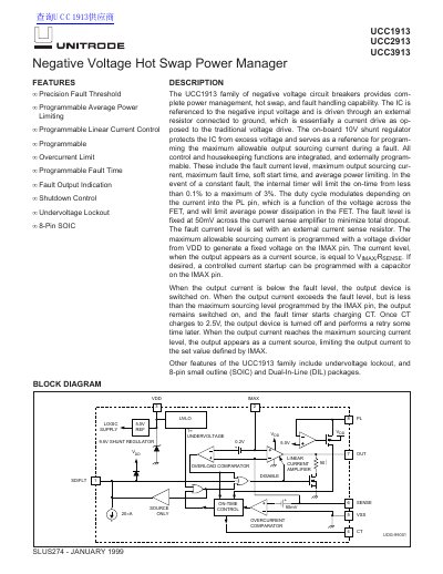
The document describes the UCC1913 family of integrated circuits designed as negative voltage circuit breakers. These devices provide complete power management, hot swap capability, and fault handling for applications requiring protection against overcurrent and overload conditions.
Key features include precision fault thresholds referenced to a negative input voltage, programmable linear current control via an external resistor, and an on-board 10V shunt regulator that protects the IC from excess voltage. The family integrates all control and housekeeping functions, allowing users to program the fault current level, maximum output sourcing current, maximum fault time, soft start time, and average power limiting.
| Overcurrent Threshold | 47.5 to 53 mV |
|---|---|
| Fault Output High Voltage | 6 to 9 V |
| Shutdown Threshold | 1.4 to 2.0 V |
| Output Duty Cycle Fault Condition | 17% to 3.7% |
The specifications apply for Ta = -55°C to +125°C.
The specifications apply for Ta = -40°C to +85°C.
The specifications apply for Ta = 0°C to +70°C.