
R1213K Series are CMOS-based, PWM control low consumption current step-up DC/DC converter ICs.
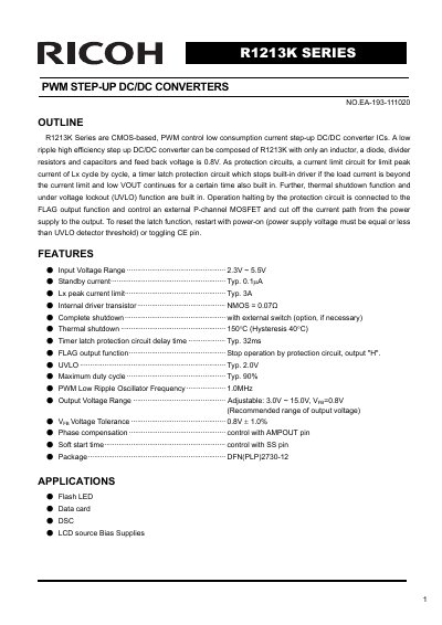
The R1213K Series are CMOS-based, PVVM control low consumption current step-up DC/DC converter ICs. They are designed to create a low ripple, high efficiency step-up converter using only an inductor, a diode, divider resistors, and capacitors. The series includes two versions: Version A for output voltages of 3.0V to 6.0V, and Version B for 6.0V to 15.0V.
The IC incorporates several protection features, including a current limit circuit, a timer latch protection circuit, thermal shutdown, and an under-voltage lockout (UVLO) function. Operation halting by these protection circuits is connected to a FLAG output function, which can control an external P-channel MOSFET to cut off the current path. The device operates with a PWM low ripple oscillator frequency of 1.0MHz and supports a maximum duty cycle of typically 90%.
| Input Voltage Range | 2.3V ~ 5.5V |
|---|---|
| Feedback Voltage | 0.8V |
| Switching Frequency | 1.0MHz |
| Maximum Duty Cycle | Typ. 90% |
| Thermal Shutdown Temperature | 150°C |
| Package Type | DFN(PLP)2730-12 |
| Lx Peak Current Limit | Typ. 3A |
The feedback voltage is 0.8V.
Recommended applications include Flash LED, Data card, bsc, and LCD source Bias Supplies.
The output voltage can be set with divider resistors for voltage setting, R1 and R2.