
TOPSwitch-II family of three terminal off-line PWM switch incorporates all functions necessary for a switched mode control system into a three terminal monolithic IC: power MOSFET, PWM controller, high voltage start up circuit, loop compensation and fault protection circuitry.
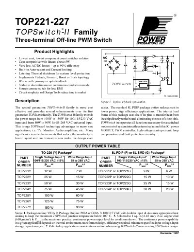
The document describes the second generation TOPSwitch-II family, which is more cost-effective than the first generation. It extends the power range to 150W for single voltage inputs (100/115/230 VAC) and 90W for wide-range universal input (85-265 VAC). The devices are suitable for applications such as TVs, monitors, and audio amplifiers.
| Power Output (Single Voltage Input) | 150W at 100/115/230 VAC |
|---|---|
| Power Output (Wide Range Input) | 90W at 85-265 VAC |
| Efficiency | Up to 90% |
| Oscillator Frequency | 100 kHz |
It brings technology advantages to new applications such as TV, Monitor, and Audio amplifiers.
The maximum practical continuous power output level reaches up to 150 W.
The device supports a single voltage input of 100/115/230 VAC and a wide range input from 85 to 265 VAC.
The shunt regulator keeps the CONTROL pin voltage at typically 5.7 V.