
The IMP525 is an Electroluminescent (EL) lamp driver designed for systems that must operate below 1 volt. It is suitable for products such as audio/TV remote control units, pagers/cellular phones, PDAs, clocks and radios, portable GPS receivers, LCD modules, and toys.
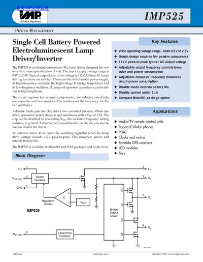
The IMP525 is an integrated circuit designed as a switch-mode power supply and high-voltage H-bridge lamp driver for systems requiring operation below one volt. It drives electroluminescent (EL) lamps with a typical output voltage of 112V peak-to-peak, suitable for applications such as audio/TV remote controls, pagers, PDAs, clocks, radios, and portable GPS receivers.
| Input Voltage Range | 0.9V to 2.5V |
|---|---|
| Typical Output Lamp Drive Voltage | 112V peak-to-peak |
| Maximum EL Lamp Capacitance | 6nF |
The device operates with an input supply voltage between 0.9V and 2.5V.
The circuit requires one inductor, one diode, one capacitor, and two resistors.
Disabling is achieved by connecting the Rew pin (oscillator frequency setting resistor) to ground.