
This design document introduces Linear Technology's LTC4440-5 and LT3782A devices for the design of a high power synchronous boost converter. The converter can be designed as a dual-phase design and does not require a heatsink.
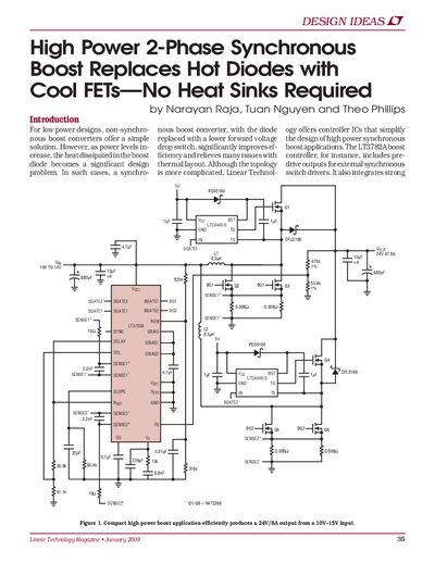
The document presents design ideas for high-power 2-phase synchronous boost converters, specifically highlighting the benefits of replacing traditional boost diodes with low forward voltage drop switches. It features application circuits utilizing the LT3782A boost controller and external drivers to achieve efficient operation without heat sinks.
The text includes detailed analysis of thermal performance comparisons between synchronous FET solutions and non-synchronous diode topologies, demonstrating significant reductions in power dissipation and board temperature at high current levels. It also covers multiphase operation advantages for reducing application size and EMI.
Synchronous converters use lower forward voltage drop switches instead of diodes, significantly improving efficiency and relieving thermal layout issues.
The circuit efficiently produces a 24V/8A output from a 10V-15V input.
The design uses a 250kHz switching frequency to optimize efficiency and component size.
This driver accepts an input voltage ranging from 9V to 36V.