
This document introduces the features and characteristics of LT3587 product. LT3587 is a 1-chip solution that combines three switching regulators and three internal high voltage switches to produce two high voltage boost converters and a single high voltage inverter. LT3587 is designed to run from inputs ranging from 2.5V to 6V, making it ideal for battery powered systems. Small package size and low component count produces a small, efficient solution. Typical applications include digital still and video cameras, high performance portable scanners and display systems, PDAs, cellular phones and handheld computers that have high voltage peripherals such as CCD sensors, LED backlights, LCD displays or OLED displays.
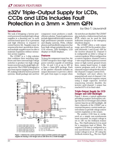
The LT3587 is designed to run from inputs ranging from 2.5V to 6V, making it ideal for battery powered systems such as digital still cameras, scanners, PDAs, and cellular phones. It integrates three high voltage power switches capable of switching up to 1A at voltages up to 32V in a small 3mm x 3mm QFN package.
The device produces two high voltage boost converters and a single high voltage inverter. Features include intelligent soft-start for sequential channel activation, output disconnects to prevent DC paths when switches are disabled, and a bidirectional fault pin (FLT) for indication or emergency shutdown.
The device runs from inputs ranging from 2.5V to 6V.
The positive channels provide an output range of up to 32V.
A fault is detected if the feedback voltage falls below its regulation value for more than 16ms.