
This document introduces the LTC 3806, a new flyback controller that improves load and cross regulation for multi-output flyback converters. Multi-output systems that previously used post regulators, multiple switching supplies or other methods to provide tight output voltage tolerances can now use lower cost flyback converters. The LTC3806 uses forced continuous conduction operation to improve cross regulation by keeping the rectifiers on and connecting the outputs to the transformer primary side, which reduces load response time and improves load regulation.
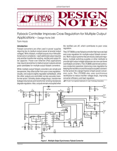
Flyback converters are often used in power supplies requiring low to medium output power at several output voltages, such as Power over Ethernet (PoE) applications. While simple and inexpensive, they often suffer from poor cross regulation due to Schottky diode voltage drops, transformer leakage inductances, and uncoupled outputs when rectifiers are off.
The LTC3806 is a new flyback controller that improves load and cross regulation for multiple output flyback converters. It uses forced continuous conduction operation to keep rectifiers on and outputs coupled via transformer action, and employs synchronous rectification to reduce voltage drops, improving efficiency and load regulation.
The LTC3806 is a flyback controller designed to improve load and cross regulation for multiple output flyback converters.
It uses forced continuous conduction operation to keep rectifiers on and outputs coupled via transformer action for a larger fraction of each power conversion cycle.
Peak efficiency for this design is 87.6% at 60% of maximum output power.