
This file is the user manual for ADM698/ADM699 microprocessor supervisory circuits. It mainly introduces the functions, features, applications and usage methods of the circuits.
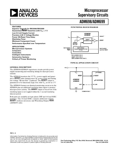
The ADM698 and ADM699 are microprocessor supervisory circuits that monitor a 5 V supply (VCC) and generate a reset pulse during power‑up, power‑down, brown‑out, or when the watchdog timer expires. The ADM698 provides voltage monitoring only, while the ADM699 adds a watchdog input to detect processor activity. Both devices guarantee a reset output that stays low even when VCC drops to 1 V.
The devices are offered in 8‑pin plastic DIP and 16‑lead SOIC packages, with the SOIC version of the ADM699 providing additional active‑high reset and watchdog output pins. Detailed specifications include operating voltage range, supply current, reset thresholds, watchdog timeout periods, and pin‑out dimensions.
| VCC Operating Voltage Range | 3.0 V – 5.5 V |
|---|---|
| Supply Current | 0.6 mA – 1.95 mA |
| Reset Threshold (typical) | 4.65 V |
| Watchdog Timeout Period (ADM699) | 1.0 s – 2.25 s |
| Reset Active Time | 140 ms – 280 ms |
The ADM698 monitors the 5 V VCC supply and generates a reset when VCC falls below the 4.65 V threshold.
The reset output remains low for a minimum of 140 ms after VCC rises above the reset threshold.
Both parts are available in 8‑pin plastic DIP and 16‑lead SOIC packages.
The watchdog timeout period is typically 1.0 s to 2.25 s at a 5 V supply.