
78Q21x3-DB MicroPHYTM MII Evaluation Board is a design example for a 10/100BASE-TX Mbit/second Fast Ethernet MII Interface adaptor
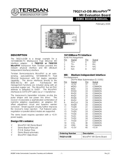
This manual describes the Teridian 78Q21x3-DB MicroPHY Evaluation Board, a design example for a 10/100BASE‑TX Ethernet PHY with MII interface. It includes a description of the board, default operation modes, and how to configure full‑ or half‑duplex operation with a Netcom master device.
Key sections cover transformer selection, PCB layout recommendations, a complete parts list, and schematic details. The document also lists recommended isolation transformers for both commercial and industrial temperature ranges and provides guidelines for EMC compliance and signal integrity.
| Transformer Turns Ratio | 1:1 |
|---|---|
| Open‑Circuit Inductance | 350 µH (min) @ 10 mV, 10 kHz |
| Leakage Inductance | 0.40 µH (max) @ 1 MHz (min) |
| Inter‑Winding Capacitance | 25 pF (max) |
| DC Resistance | 0.9 Ω (max) |
| Insertion Loss | 1.1 dB (typ) 0‑100 MHz |
| HIPOT Rating | 1500 Vrms |
| Default PHY Address | 0x001 |
The MicroPHY defaults to the PHY address 0x001.
The MicroPHY will auto‑negotiate to half‑duplex if the connected transceiver defaults to half‑duplex, or you can configure it via the control register MRO bits.
A pair of 1:1 isolation transformers with specifications such as 350 µH open‑circuit inductance and 0.9 Ω DC resistance are required.
Use 100 Ω differential transmission lines, place termination components near the transceiver pins, keep differential pairs short and matched, and provide thorough decoupling with low‑inductance capacitors.