
The MAX1270/MAX1271 are multirange, 12-bit data-acquisition systems (DAS) that require only a single +5V supply for operation. These systems provide eight analog input channels that are independently software programmable for a variety of ranges: ±10V, ±5V, 0 to +10V, 0 to +5V for the MAX1270; ±VREF, ±VREF/2, 0 to VREF, 0 to VREF/2 for the MAX1271. This range switching increases the effective dynamic range to 14 bits and provides the flexibility to interface 4-20mA, ±12V, and ±15V powered sensors directly to a single +5V system. In addition, these converters are fault protected to ±16.5V. A fault condition on any channel will not affect the conversion result of the selected channel. Other features include a 5MHz bandwidth track/hold, software-selectable internal/external clock, 110ksps throughput rate, and internal 4.096V or external reference operation. The MAX1270/MAX1271 serial interface directly connects to SPI™/QSPI™ and MICROWIRE™ devices without external logic. A hardware shutdown input (SHDN) and two software-programmable power-down modes, standby (STBYPD) or full power-down (FULLPD), are provided for low-cur- rent shutdown between conversions. In standby mode, the reference buffer remains active, eliminating startup delays. The MAX1270/MAX1271 are available in 24-pin narrow PDIP or space-saving 28-pin SSOP packages.
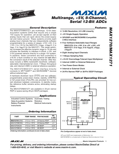
The MAX1270/MAX1271 are multirange, 12‑bit data‑acquisition systems that operate from a single +5 V supply. They provide eight independently programmable analog input channels and support a variety of input ranges for both bipolar and unipolar operation.
Key features include ±16.5 V over‑voltage protection, internal 4.096 V reference (or external), two power‑down modes (standby and full), 5 MHz track‑and‑hold bandwidth, and serial interfaces compatible with SPI/QSPI and MICROWIRE. The devices are offered in 24‑pin PDIP or 28‑pin SSOP packages.
| Resolution | 12 bits |
|---|---|
| Sampling Rate | 110 ksps (MAX1270B) / 100 ksps (MAX1270A) |
| Analog Input Channels | 8 |
| Input Ranges (MAX1270) | ±10 V, ±5 V, 0‑to +10 V, 0‑to +5 V |
| Input Ranges (MAX1271) | ±VREF, ±VREF/2, 0‑to VREF, 0‑to VREF/2 |
| Over‑voltage Protection | ±16.5 V |
| Supply Voltage | +5 V single‑supply |
| Power‑down Modes | Standby (STBYPD) and Full Power‑down (FULLPD) |
| Reference Voltage | Internal 4.096 V or external |
| Package Options | 24‑Pin Narrow PDIP or 28‑Pin SSOP |
Both devices operate from a single +5 V supply.
The ADCs provide eight independently programmable analog input channels.
The MAX1270 supports ±10 V, ±5 V, 0‑to +10 V, and 0‑to +5 V ranges.
Two software‑programmable power‑down modes are available: standby (STBYPD) and full power‑down (FULLPD).