
The LTC1473 provides a power management solution for single and dual battery notebook computers and other portable equipment. The LTC1473 drives two sets of back-to-back N-channel MOSFET switches to route power to the input of the main system switching regulator. An internal boost regulator provides the voltage to fully enhance the logic level N-channel MOSFET switches. The LTC1473 senses current to limit surge currents both into and out of the batteries and the system supply capacitor during switch-over transitions or during fault conditions. A user-programmable timer monitors the time the MOSFET switches are in current limit and latches them off when the programmed time is exceeded. A unique “2-diode mode” logic ensures system start-up regardless of which input receives power first.
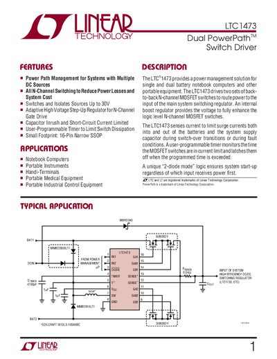
This manual introduces the LTC1473, a dual‑battery power‑path management solution for notebook computers and other portable equipment. It describes the device’s architecture, including back‑to‑back N‑channel MOSFET switches, an internal boost regulator, and adaptive inrush‑current limiting.
The document provides detailed pin descriptions, functional diagrams, typical application circuits, electrical characteristics, absolute maximum ratings, and package dimensions. It also includes application notes on hot‑swap operation, gate‑drive requirements, and related Linear Technology parts.
| Supply Operating Range | 4.75 V – 30 V |
|---|---|
| Package | 16‑Lead Narrow SSOP |
The TIMER pin provides a fault timer; a capacitor to ground programs how long the MOSFET switches may stay in current‑limit before latching off.
V* is the input supply pin and should be bypassed with at least a 1 pF capacitor.