
This DC motor driver module is suitable for small DC motors, relays, stepper motors and switch power supply transistors, and can realize motor forward and reverse rotation.
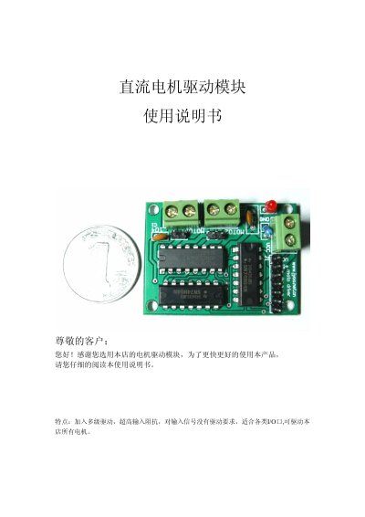
The manual introduces a compact DC motor driver module designed for small‑current DC motors, stepper motors, relays and other loads. It highlights the use of an L293 H‑bridge chip, multi‑stage drive, high input resistance and compatibility with various I/O ports.
Detailed pin descriptions cover power supply indicators, motor power terminals, 5 V logic supply, ground, direction and speed control pins (M1, M2), and their wiring options. The document also explains PWM speed control, logic level requirements, and recommended connection methods for safe operation. This manual is written in Chinese.
| Control Chip | L293 H‑bridge |
|---|---|
| Output Current per Channel | 1000 mA |
| Maximum Continuous Current | 2 A |
| Maximum Working Voltage | 36 V |
| Logic Power Supply | 5 V |
| PWM Frequency Minimum | ≥ 100 kHz |
| PWM Duty Cycle Range | 0‑100 % |
The module can operate up to a maximum working voltage of 36 V.
Connect the M1 or M2 direction pin to a microcontroller I/O; a high level makes the motor turn forward, a low level makes it reverse.
The PWM input must have a frequency of at least 100 kHz and can use a 0‑100 % duty cycle.