
This document introduces the features, interface indications and usage methods of the DC motor driver module, and provides usage precautions.
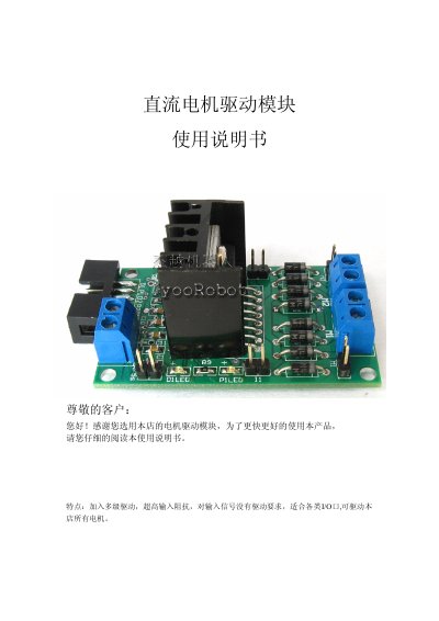
The DC motor drive module is designed for small‑to‑medium DC motors, relays, stepper motors and switching‑power transistors. It uses an L298 H‑bridge IC, provides up to 2 A continuous output (4 A peak) and can operate from a supply voltage of up to 36 V. The module includes a 10‑pin header for easy connection to a microcontroller and supports PWM speed control up to 100 kHz.
The manual describes the pin functions, power‑LED indicators, current‑sense interfaces, and high‑power output terminals. It also explains how to control motor direction and speed via MCU I/O pins, and gives wiring recommendations such as sharing a 5 V supply between the module and the motor power source. This manual is written in Chinese.
| Maximum Continuous Output Current | 2 A (peak 4 A) |
|---|---|
| Maximum Supply Voltage | 36 V |
| PWM Frequency Capability | ≥100 kHz, 100 % duty |
| Connector Type | 10‑pin header (compatible with DuPont wires) |
| System Power Supply | +5 V |
The module can be powered with a voltage up to 36 V.
The module accepts PWM signals up to at least 100 kHz with 0‑100 % duty cycle.
Yes, it provides two independent motor channels (M1 and M2) with separate direction and speed control pins.