
WAT12 Analog Wind Transmitter User's Guide, introduces information about product installation, use and maintenance
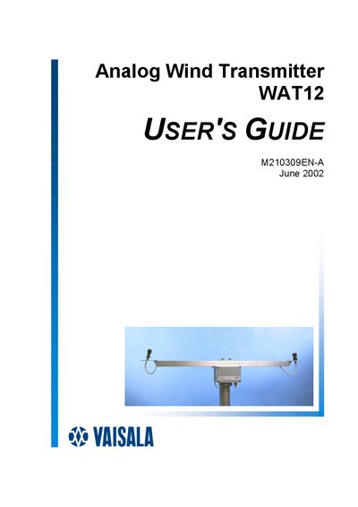
This manual gives complete information for installing and maintaining the WAT12 analog wind transmitter, including safety considerations, wiring, and calibration procedures.
It is organized into chapters covering general information, product overview, installation, maintenance, troubleshooting, and technical data, with detailed specifications, wiring diagrams, and a parts list for consumables.
| Equipment type | Digital-to-analog current loop converter for Vaisala wind sensors |
|---|---|
| Signal input (direction) | 6-bit parallel GRAY code (optionally 7 bits) |
| Wind speed signal | Pulse frequency 0…750 Hz |
| Input operating power | 12…28 VDC, 30 mA |
| Output sensor power | On‑board regulated to 10.7 VDC (typical) |
| Output signals | Two analog current loops (direction and speed) |
| Loop driving voltage | 10 V (typical) |
| Maximum loop resistance (5 mA) | 1800 Ω |
| Full‑scale direction range | 0…360° / 0…540° |
| Full‑scale speed range | 0…51.2 m/s / 0…76.8 m/s |
| Resolution (direction) | ±2.8° |
| Resolution (speed) | ±0.1 m/s |
| Output accuracy | Better than 1 % of full scale |
| Operating temperature range | -55 °C … +55 °C |
| Ingress protection | IP65 |
| Weight | 1.5 kg |
The signal cable requires a minimum of four wires: VIN+, VIN‑, DOP, and SOP.
The maximum loop resistance for a 5 mA loop is 1800 Ω.
The WAT12 operates from –55 °C to +55 °C.