
The TL494 is a pulse-width modulation power controller with high integration and complete functions. It can provide 200 mA output current, single-ended or push-pull operation, variable dead time and a stable 5 V reference supply. The circuit architecture is easy to synchronize
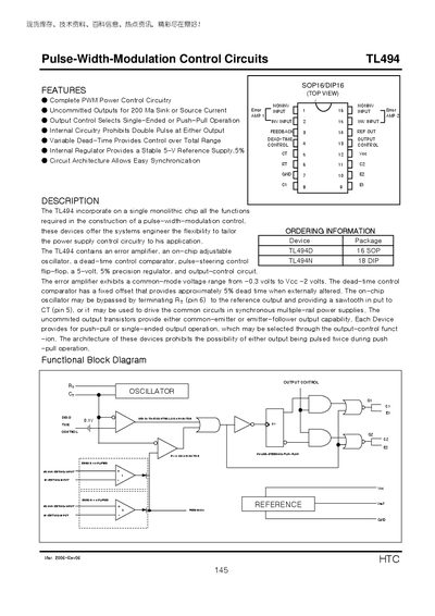
The TL494 integrates PWM control functions on a single monolithic chip, offering a complete power‑control circuitry with uncommitted outputs, dead‑time control, and an internal 5 V reference regulator. It supports both single‑ended and push‑pull output configurations and includes an on‑chip oscillator that can be synchronized or bypassed.
The document lists absolute maximum ratings, recommended operating conditions, electrical characteristics, and switching performance. Test circuits and waveform examples illustrate typical operation, and detailed tables give values for supply voltage, output current, timing components, oscillator frequency, and temperature ranges.
| Supply voltage (absolute max) | 41 V |
|---|---|
| Supply voltage (recommended) | 7 V to 40 V |
| Collector output current (absolute max) | 250 mA |
| Collector output current (recommended per transistor) | 200 mA |
| Oscillator frequency | 1 kHz to 300 kHz |
| Operating free‑air temperature range | 0 °C to 70 °C |
| Output voltage rise time (common‑emitter) | 100 ns to 200 ns |
| Input offset voltage (pin 3) | 2 mV to 10 mV |
The absolute maximum supply voltage (Vcc) is 41 V.
The recommended operating supply voltage is between 7 V and 40 V.
Each output transistor can handle up to 200 mA under recommended conditions, with an absolute maximum of 250 mA.
The oscillator can operate from 1 kHz up to 300 kHz.