
This document provides a detailed introduction to the features of the AVR XMEGA microcontroller, including memory, DMA controller, timer/counter, serial port, I2C, SPI, AES and DES crypto engine, real-time counter, analog/digital converter, comparator, watchdog timer, etc.
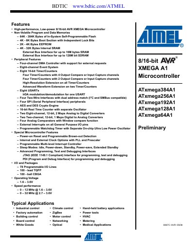
The ATxmega64A1 is a low‑power, high‑performance 8/16‑bit AVR microcontroller with a rich set of peripherals, including four DMA channels, eight USARTs, multiple timers, ADCs, DACs, and a crypto engine. It offers up to 384 KB of Flash, 32 KB of SRAM, and 78 programmable I/O lines in compact TQFP or CBGA packages.
The datasheet includes a detailed block diagram, pin‑out tables, memory maps, clock options, power‑management modes, and debugging interfaces (JTAG and PDI). It also lists packaging information, electrical characteristics, and revision history for developers and system designers.
| Operating Voltage | 1.6 V – 3.6 V |
|---|---|
| Maximum Clock Frequency | 0 – 12 MHz @ 1.6‑3.6 V, 0 – 32 MHz @ 2.7‑3.6 V |
| Flash Memory | 64 KB – 384 KB |
| EEPROM | 2 KB – 4 KB |
| SRAM | 4 KB – 32 KB |
| Programmable I/O Pins | 78 |
| Package Types | 100‑lead TQFP, 100‑ball CBGA |
The device supports JTAG (IEEE 1149.1 compliant) and PDI (Program and Debug Interface) for programming and debugging.
It includes a four‑channel DMA controller.