
ADM696/ADM697 is a microprocessor supervisory circuit with upgraded performance and features.
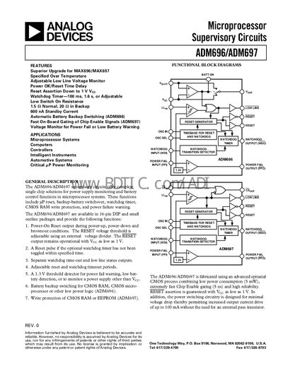
The ADM696 and ADM697 are single‑chip supervisory circuits that provide power‑on reset, watchdog timer, low‑line monitoring, battery backup switching and RAM write protection for microprocessor systems. They are offered in 16‑pin DIP and SOIC packages and operate from 3 V to 5.5 V.
The document includes functional block diagrams, absolute maximum ratings, detailed pin descriptions, circuit information for battery switchover, reset and watchdog operation, as well as ordering information and mechanical dimensions.
| Operating Voltage Range | 3.0 V – 5.5 V |
|---|---|
| Supply Current (no backup) | 1 – 1.95 mA (at 100 mA load) |
| Reset Timeout Delay | 35 – 70 ms |
| Watchdog Timeout (internal oscillator) | 1.0 s – 2.25 s (adjustable) |
| Low Line Threshold (Llyn) | 1.25 V – 1.35 V (typ. 1.3 V) |
The devices operate from 3.0 V up to 5.5 V.
The reset timeout can be set to 35 ms, 50 ms, or 70 ms depending on the configuration.
The internal watchdog can be programmed for a short 100 ms period, a long 1.6 s period, or an adjustable range from 1.0 s to 2.25 s.
The low‑line threshold is typically 1.3 V, with a range of 1.25 V to 1.35 V.