
Drivecon Inc. reserves the right to alter or amend the above information without notice. Before starting, read carefully instructions and this table. Verify all connections are according to drawings. Verify motor supply is connected correctly, wrong connection will destroy the inverter. Verify internal voltage selections of device are correct. Check device cover is properly installed and all ventilation holes are clear and uncovered. Check that hot air coming from brake resistors does not cause any danger. High voltages are present in this device. Do not make any inspections unless the supply has been disconnected by main switch. Before opening the device cover, wait at least 5 minutes after the display lamps turn off. Insulation resistance test with a megger requires special precautions. Do not make any measurements inside the device when it is connected to main supply. Do not touch the IC-circuits on the circuit boards. Static voltage discharge may destroy the components. It is forbidden to use radiophones and portable phones near this device with the doors open. All the doors and covers must be closed during crane in operation.
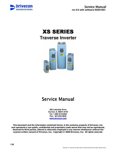
This manual covers the Drivecon XS Series traverse inverter, describing its technical data, main components, control methods, and safety precautions. It is intended for service technicians who need detailed instructions for installation, parameter setting, and fault diagnosis.
Key sections include general information, installation wiring, component descriptions, parameter adjustments, start‑up procedures, and a comprehensive troubleshooting table with fault codes. The document also outlines mechanical brake operation and EMC requirements.
| Horsepower (Hp) at 460V | 3–30 HP |
|---|---|
| Output current (A) | 5.0–48 A |
| Supply voltage | 380‑500 VAC |
| Frequency control range | 0 … 250 Hz |
| Speed accuracy | 1 % of nominal speed |
| Braking torque | 150 % of rated torque |
| Ambient temperature operating range | -10 °C … +50 °C |
The manual rev 6.0 is for XS rev 1.0 with software D2S2V051.
When a fault occurs, the display shows a blinking code “F1 xx” and the fault indicator lights on.
The inverter supports three control methods: EP (electronic potentiometer), MS (multistep), and AU (automation) with various modes selectable via parameter P1.1.11.