
This document is the wiring instructions for Toshiba V Series Computer Link human machine, including communication speed, controller station number, control area/status area, controller wiring terminal and read/write address definition.
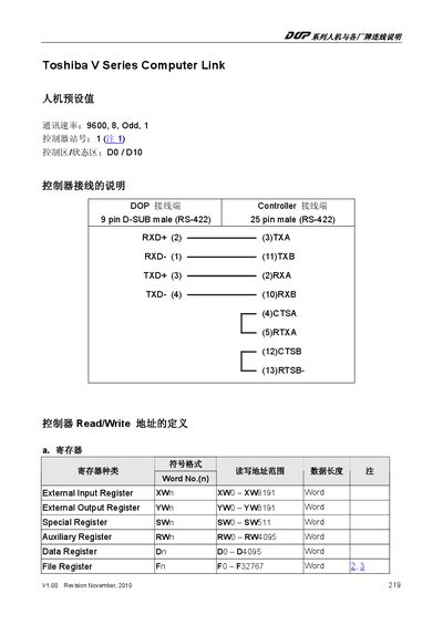
This manual describes the hardware connection and register map for the Toshiba V Series Computer Link. It includes pin assignments for the 9‑pin and 25‑pin RS‑422 connectors and explains how to access the various registers.
The document lists the address ranges for external input/output registers, special registers, auxiliary registers, data registers, and file registers, allowing developers to read and write values correctly.
| Connector Types | 9‑pin D‑SUB male (RS‑422) and 25‑pin male (RS‑422) |
|---|---|
| External Input Register Range | X0 – X8191 (Word) |
| External Output Register Range | Y0 – Y8191 (Word) |
| Special Register Range | S0 – S511 (Word) |
| Auxiliary Register Range | R0 – R4095 (Word) |
| Data Register Range | D0 – D4095 (Word) |
| File Register Range | F0 – F32767 (Word) |
It uses a 9‑pin D‑SUB male (RS‑422) and a 25‑pin male (RS‑422) connector.
The Data Register spans addresses D0 to D4095.
The Special Register provides 512 words, from S0 to S511.
The manual is revision V1.00 dated November 2010.