
The AD9981 evaluation board is part of the AD9981 evaluation kit and can be used to evaluate the AD9981 performance or as an implementation example for an end-user evaluation platform using the 100-pin interface connector.
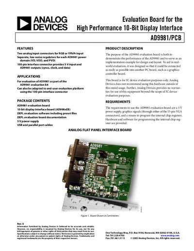
The AD9981/PCB evaluation board is designed to demonstrate the performance of the AD9981 10‑bit display interface IC and to provide a reference implementation for design and layout. It includes two analog input connectors for RGB or YPbPr signals, separate low‑noise regulators for each power domain, and a 100‑pin connector for power and AD9981 I/O.
The board requires a 5 V supply and can be programmed via provided hardware (standard printer cable) and software (DEPL evaluation software). Detailed sections describe hardware configuration, register programming, software installation, sample settings, schematics, and ordering information.
| Analog input connectors | Two connectors for RGB or YPbPr input |
|---|---|
| Power regulators | Separate low‑noise regulators for VD, VDD, and PVD; two 3.3 V regulators and an adjustable 1.8 V regulator |
| Interface connector | 100‑pin connector provides 5 V input and AD9981 outputs (syncs, clock, data) |
| Required power supply | 5 V DC |
The board needs a 5 V power supply, which is applied through the right‑side connector (Pins 1‑4 of J3).
Programming is done with provided hardware (a standard printer cable and a receiver chip) and the DEPL evaluation software; signals are routed via Pins 7 and 9 on connector J3.
The DEPL evaluation software, a Visual Basic program for Windows 95 or later, is supplied on a self‑installing CD and allows full register control.