
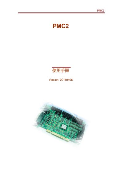
This manual describes the hardware layout of the PMC2 controller, including the pin‑out tables for scan heads, laser connectors, motor drivers, encoders and various I/O ports. Each connector is identified with its pin count and signal function, and the document lists the required power supplies and jumper settings.
The later sections cover analog output configuration, laser modulation signals, SPI and IPG interfaces, and detailed wiring diagrams for integrating the PMC2 into a laser processing system. Reference tables and diagrams help technicians set up and troubleshoot the device.