
This manual introduces the specifications, appearance, pin configuration, installation and wiring of the PMC2 control card, and the appearance and pin configuration of the DA2-16 daughter card.
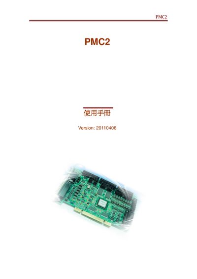
This manual describes the hardware layout, connector pin assignments, and jumper settings for the PMC2 system. It includes detailed tables for scan heads, laser connectors, motor drivers, encoders, and I/O modules.
Later sections cover analog and digital output configurations, laser control signals, IPG and SPI settings, and parameter adjustment procedures. The document also lists version information and reference diagrams for troubleshooting and system integration.
| Version | 20110406 |
|---|---|
| SCANHEAD1 connector pin count | 25‑pin |
| Laser type | ROS |
| Power Level (example) | 98 |
The manual is dated Version 20110406.
The SCANHEAD1 connector uses a 25‑pin D‑SUB connector.
The document lists the laser type as ROS.