
Datasheet for the STMicroelectronics L6574 high-voltage ballast driver IC designed for fluorescent lamp applications with half-bridge topology.
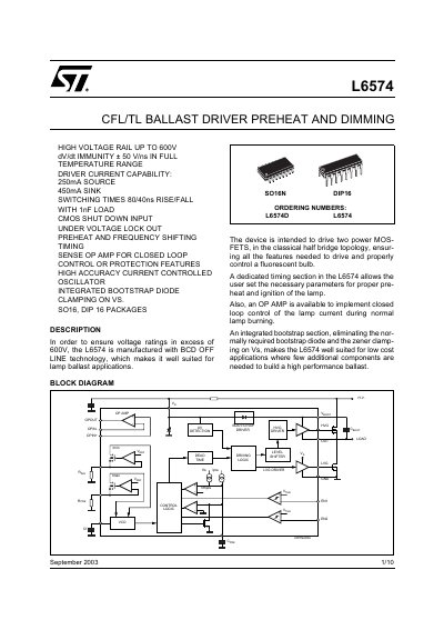
The L6574 is a high-voltage ballast driver manufactured using BCD offline technology, designed specifically for fluorescent lamp applications. It features a half-bridge topology capable of driving two power MOSFETs to ensure proper preheat and ignition of the lamp. The device includes an operational amplifier for closed-loop control of lamp current and an integrated bootstrap section to eliminate the need for external bootstrap diodes and zener clamping on Vs.
| Supply Voltage | 10 to 600 V |
|---|---|
| dV/dt Immunity | ± 50 V/ns |
| Driver Current Capability (Source) | 250 mA |
| Driver Current Capability (Sink) | 450 mA |
| Switching Times (Rise/Fall) | 80/40 ns |
| Storage Temperature | -40 to +150 °C |
| Ambient Temperature | -40 to +125 °C |
| Output Duty Cycle | 48 to 52 % |
| Op Amp Gain Band Width Product | 1 MHz |
| Op Amp DC Open Loop Gain | 80 dB |
| Enable Comparators Threshold | 0.56 to 0.64 V |
| Enable Comparators Hysteresis | 20 to 100 mV |
| Minimum Pulse Length | 200 ns |
| Dead Time | 0.8 to 1.7 µs |
| Package Types | SO16, DIP 16 |
The device is manufactured with BCD offline technology to ensure voltage ratings in excess of 600V.
Yes, it features an integrated bootstrap section that replaces the normally required external bootstrap diode and zener clamping on Vs.
The preheat time is set by connecting a capacitor to the Cpre pin, calculated using the formula tpre=kpre*Cpre.