
This guide details the usage of the BRD4174B EFR32MG13 Radio Board with the Wireless Starter Kit Mainboard, covering hardware, connectors, and peripherals.
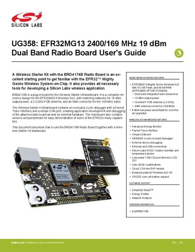
This document describes the EFR32MG13 2400/169 MHz 19 dBm Dual Band Radio Board (BRD4174B) and its operation when combined with the Wireless Starter Kit Mainboard. The kit serves as a reference design for the EFR32MG13 Wireless SoC, featuring a complete hardware setup with matching networks for 19 dBm output power and dual-band antennas.
The guide covers the hardware layout, block diagram, and detailed descriptions of all connectors including the J-Link USB, Ethernet, and expansion headers. It also explains the power supply options, reset procedures, and the functionality of on-board peripherals such as the Advanced Energy Monitor, virtual COM port, and sensors.
| SoC Flash Memory | 512 kB |
|---|---|
| SoC RAM | 64 kB |
| Output Power | 19 dBm |
| Serial Flash | 8 Mbit |
| Antenna Type (2.4 GHz) | Inverted-F PCB antenna |
| Antenna Connector (169 MHz) | SMA connector |
The part number for the board is BRD4174B.
It is recommended that the USB host be able to supply at least 500 mA.
No, the kit cannot be powered using the Ethernet connector; the USB connector must be used for power.