
The Renogy PWM10CC manual provides specifications, installation steps, lighting control options, LED indicators, troubleshooting, and maintenance guidance.
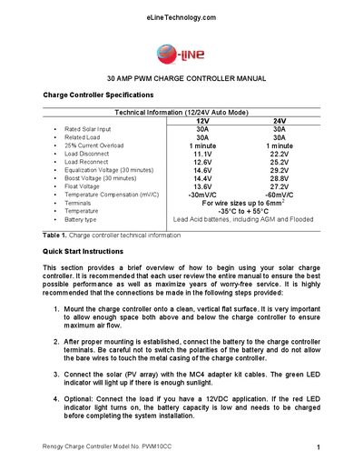
This manual covers the technical specifications of the Renogy PWM10CC 30 A PWM charge controller, including rated solar input, load limits, voltage settings, temperature compensation, and compatible battery types. It also provides a quick‑start guide for mounting, wiring the battery, solar panel, and optional load.
Further sections explain lighting control modes, LED indicator meanings, troubleshooting tips for common LED alerts, and a yearly inspection and maintenance checklist to ensure reliable operation.
| Rated Solar Input | 30 A (12 V) / 30 A (24 V) |
|---|---|
| Related Load | 30 A (12 V) / 30 A (24 V) |
| 25% Current Overload | 1 minute |
| Load Disconnect Voltage | 11.1 V (12 V) / 22.2 V (24 V) |
| Load Reconnect Voltage | 12.6 V (12 V) / 25.2 V (24 V) |
| Equalization Voltage (30 min) | 14.6 V (12 V) / 29.2 V (24 V) |
| Boost Voltage (30 min) | 14.4 V (12 V) / 28.8 V (24 V) |
| Float Voltage | 13.6 V (12 V) / 27.2 V (24 V) |
| Temperature Compensation | -30 mV/°C (12 V) / -60 mV/°C (24 V) |
| Maximum Wire Size | 6 mm² |
| Operating Temperature Range | -35 °C to +55 °C |
| Battery Type | Lead‑acid (AGM and Flooded) |
The green LED should be ON, showing that solar power is charging the battery.
Press the SET button; the controller will resume operation after about 10 seconds (or up to a few minutes).
Power on the controller and press the SET button until the number 17 appears; this indicates proper connections.
Check that the load is on, verify fuses, inspect connections for voltage drop, and ensure the load is not exceeding the rated power.