
Power-Rail PR6850C Isolated AC-DC Switch Power Supply Design Guide

A design guide for the PR6850C isolated AC-DC switch power supply chip, covering features, working principles, and transformer design calculations.
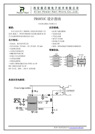

Power-Rail PR6850C Isolated AC-DC Switch Power Supply Design Guide - cover page
Brand
Power-Rail
Category
Power Management
Document type
Datasheet
Language
English
Pages
10
File format
PDF
File size
724 KB
Published
16 October, 2026
Updated
16 October, 2026
MD5 checksum
BDFD3E5238510EBBBF57E59652701D5B

About this manual

This document serves as a design guide for the PR6850C, an integrated chip used in isolated AC-DC switch power supplies. It highlights key features such as low startup current (approx 8µA), current mode control with built-in synchronous slope compensation, and adjustable PWM frequency. The guide supports applications including AC/DC adapters, battery chargers, and set-top box power supplies.

What's inside

  • Chip Features
  • Application Fields
  • System Specifications
  • Input Rectification Design
  • Transformer Core Selection
  • Winding Calculations
  • Feedback Loop Design

Frequently asked questions

What is the recommended range for setting the reflected voltage VOR in a continuous conduction mode design?

The document recommends setting the reflected voltage between 60V and 80V to ensure the maximum duty cycle does not exceed 0.5.

What is the suggested minimum DC voltage for the auxiliary winding under no-load conditions?

The guide suggests setting the auxiliary winding voltage greater than 11.5V to prevent false triggering of UVLO during load transitions.

Download PDF (724 KB)