
Key facts
- Manuals
- 1
- Languages
- EN
- Last added
- 2026-10-16
Featured Power-Rail manuals
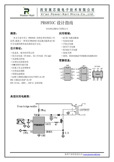
Power-Rail PR6850C Isolated AC-DC Switch Power Supply Design Guide
This document serves as a design guide for the PR6850C, an integrated chip used in isolated AC-DC switch power supplies. It highlights key features such as low startup current (approx 8µA), current mode control with built-in synchronous slope compensation, and adjustable PWM frequency. The guide supports applications including AC/DC adapters, battery chargers, and set-top box power supplies.
Covers: Chip Features · Application Fields · System Specifications · Input Rectification Design · Transformer Core Selection · Winding Calculations
Latest Power-Rail manuals
Power-Rail PR6850C Isolated AC-DC Switch Power Supply Design Guide
Datasheet 10 pages · 724 KB · ENA design guide for the PR6850C isolated AC-DC switch power supply chip, covering features, working principles, and transformer design calculations.
Which document do I need?
Datasheet
Ratings, dimensions and ordering codes, for selection and design work.
Questions answered in Power-Rail manuals
What is the recommended range for setting the reflected voltage VOR in a continuous conduction mode design?
The document recommends setting the reflected voltage between 60V and 80V to ensure the maximum duty cycle does not exceed 0.5.
From: Power-Rail PR6850C Isolated AC-DC Switch Power Supply Design Guide
What is the suggested minimum DC voltage for the auxiliary winding under no-load conditions?
The guide suggests setting the auxiliary winding voltage greater than 11.5V to prevent false triggering of UVLO during load transitions.
From: Power-Rail PR6850C Isolated AC-DC Switch Power Supply Design Guide