
Instruction and operating manual for Power-Genex Foundation Fieldbus function block and transducer block design, covering block parameters, attribute…
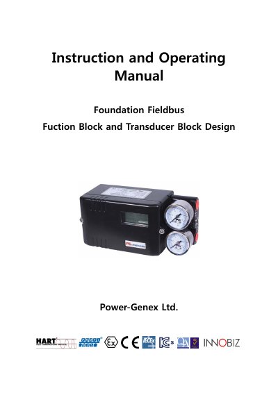
This manual documents the Foundation Fieldbus function block and transducer block design implemented in Power-Genex field devices. It details the Resource Block (RB2), Positioner Transducer Block (POS_TB), Analog Input Blocks (AI1, AI2), Analog Output Block (AO), Discrete Input Blocks (DI1, DI2), and PID Control Block, listing all block parameters with their indices, mnemonics, and view sizes.
The document also defines parameter attributes for function blocks, the Field Diagnostics Profile, transducers, and user-defined structures including ZERO_SPAN, PID_PARAMETERS, and USER_ALARM. Detailed parameter descriptions cover transducer channels, valve stroke test settings, calibration data, and actuator/valve configuration parameters.
The manual covers Resource (RB2), Positioner Transducer (POS_TB), Analog Input (AI1, AI2), Analog Output (AO), Discrete Input (DI1, DI2), and PID control blocks.
Five channels are defined: AI1 (Actual Position), AI2 (Temperature), AO (Command Position), DI1, and DI2.
Yes, it describes PST (Partial Stroke Test) parameters including interval, ramp rate, target travel, and timeout settings, as well as VST command and result parameters.