
User manual for the PEAK-System PCAN-Router FD covering hardware configuration, connectors, operation, firmware development and upload, and technical data.
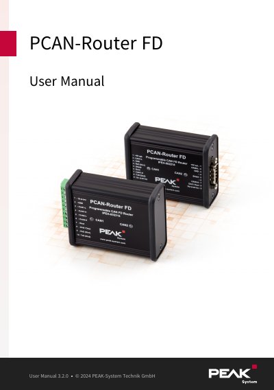
The PCAN-Router FD connects to two CAN FD or CAN buses and routes data between them. Based on an ARM Cortex-M4F microcontroller, its behavior and data routing are freely programmable, including conversion between CAN and CAN FD.
The manual describes the D-Sub and screw-terminal variants, hardware configuration options, operation and status LEDs, creating and uploading firmware, technical data, and conformity and disposal information.
| Microcontroller | NXP LPC4078 (ARM Cortex-M4 with FPU, 120 MHz) |
|---|---|
| On-chip EEPROM | 4 kByte |
| SPI flash | 8 MByte |
| CAN channels | 2 high-speed CAN channels (ISO 11898-2) |
| CAN protocols | CAN FD ISO 11898-1:2015, CAN FD non-ISO, CAN 2.0 A/B |
| CAN FD data field bit rate | 40 kbit/s to 12 Mbit/s (64 bytes max.) |
| CAN bit rate | 40 kbit/s to 1 Mbit/s |
| CAN transceiver | NXP TJA1043T with wake-up |
| CAN termination | Activatable through solder jumpers, separately for each CAN channel |
| Connectors (IPEH-002214) | 2 x 9-pin D-Sub (male) |
| Connectors (IPEH-002215) | 10-pole screw terminal block |
| Terminal block pitch | 3.81 mm |
| RS-232 | 1 x D-Sub (CAN1, pins 4 and 8) |
| External device supply | +5 V (optional) |
| Digital I/O | 1 digital input (low-active), 1 digital output (low-side switch, max. 600 mA); 2 additional digital inputs alternatively to RS-232 |
| Status indication | 2 two-color LEDs |
| Casing | Aluminum casing, optional DIN rail fixing |
| Supply voltage | 8 to 30 V DC (12 V DC nominal) |
| Current consumption | Idle 75 mA at 12 V; max. 150 mA at 8 V, 100 mA at 12 V, 50 mA at 30 V |
| Power-saving modes | Power-down mode with 40 µA |
| Protection | ±1 kV surge, -60 V reverse polarity, ±4 kV ESD |
| Operating temperature | -40 to +85 °C (-40 to +185 °F) |
| Firmware upload | Via CAN interface |
The module requires a supply voltage from 8 to 30 V DC.
The extended operating temperature range is -40 to +85 °C.
It provides two high-speed CAN channels.
Yes, new firmware can be loaded via the CAN interface.