
Installation and user guide for the NetThings Energy Manager: CT and pulse channel wiring, Wi-Fi pairing, commissioning, and M-Bus setup.
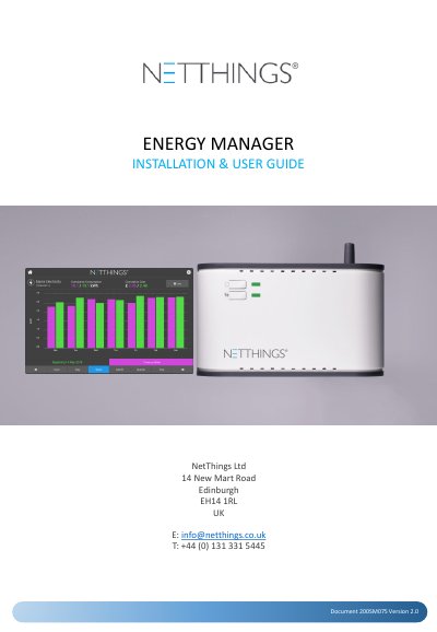
This is the NetThings Energy Manager installation and user guide, published by NetThings Ltd in Edinburgh as document 200SM075, version 2.0. It walks through an eight-step installation, the wiring of the controller's channels, commissioning the Energy Manager from the display, everyday use of the display, and additional information and specifications, plus appendices on M-Bus installation and Evinox integration.
The guide describes the Energy Manager as a mains powered energy monitoring solution made up of a controller and a mounted display that are linked by WiFi with no cables between them. Electricity is monitored through current transducers or a pulse connection, and gas, water and heating through pulse and M-Bus inputs where fitted. It covers pairing with WPS or with the SSID and password, setting up electricity and pulse channels, activating the configuration, and reading current and historical consumption on the display.
| Power supply | 3A Switched Fused Spur, marked to show its purpose and easily accessible |
|---|---|
| Controller to display link | WiFi, no cables required between controller and display |
| Maximum display to controller distance | 5 metres |
| Pulse cable type | Belden 9501 or equivalent |
| Channel inputs | Channels 1 to 3 for current transducers, channels 4 and 5 pulse only, channel 6 pulse and M-Bus |
| Supported M-Bus meter manufacturers | Diehl, GWF, Kamstrup, Sontex, Danfoss |
| Mounting | Recessed 2-gang pattress box for both controller and display |
| Display sizes | 5 inch and 7 inch |
The distance between the display and the controller should not exceed 5 metres, because solid walls and obstructions can affect the WiFi signal.
Press and hold the # button on the Energy Manager for 3 seconds until its LED turns solid green and release it, then press the WPS symbol on the display screen.
It is powered via a 3A Switched Fused Spur that is marked to show its purpose and is easily accessible.
Diehl, GWF, Kamstrup, Sontex and Danfoss M-Bus meters are supported for use with the Energy Manager.