
MGS Series guide for selecting power and Modbus communications cable sizes for MGS gas detection controllers and detectors.
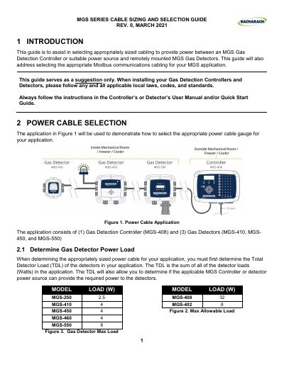
This MGS Series guide explains how to select power and Modbus communications cabling between an MGS Gas Detection Controller or suitable power source and remotely mounted MGS Gas Detectors.
It covers calculating total detector load, checking controller minimum output voltage and detector minimum input voltage, calculating power cable voltage drop, and selecting cable gauge. It also addresses Modbus cable selection, cable gland sizes, wire terminations, cable recommendations, and a single cable application.
| MGS-408 maximum allowable load | 32 W |
|---|---|
| MGS-410 minimum input voltage | 19.5 VDC |
| MGS-408 nominal voltage and tolerance | 24 VDC, +/- 2.5% |
| Modbus communication cable maximum length | 1,000 ft |
| MGS-408 cable gland sizes | (2) M20, (6) M16 |
| Recommended cable impedance | 120 Ω |
The total detector load is the sum of all detector loads in watts in the application.
The Modbus communication cable to the furthest detector is limited to 1,000 ft maximum.
The example application requires 14 AWG power wire so the input voltage at the furthest detector exceeds its minimum input voltage.
A 120 Ω impedance is recommended for all MGS units; 100 Ω is acceptable when using the listed cables.