
Key facts
- Manuals
- 1
- Languages
- EN
- Last added
- 2026-11-16
Featured MGS manuals
MGS Series Gas Detection Cable Sizing and Selection Guide
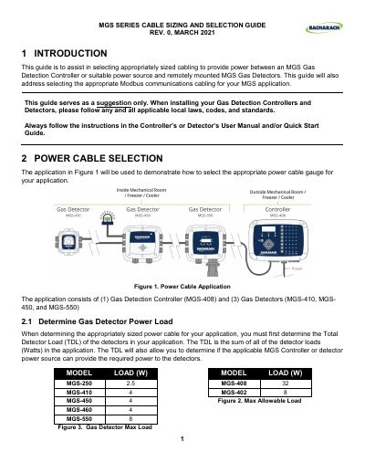
This MGS Series guide explains how to select power and Modbus communications cabling between an MGS Gas Detection Controller or suitable power source and remotely mounted MGS Gas Detectors.
It covers calculating total detector load, checking controller minimum output voltage and detector minimum input voltage, calculating power cable voltage drop, and selecting cable gauge. It also addresses Modbus cable selection, cable gland sizes, wire terminations, cable recommendations, and a single cable application.
Covers: Introduction · Power Cable Selection · Determine Gas Detector Power Load · Power Wire Gauge Size · Modbus Communications Cable Selection · Cable Gland Size
Latest MGS manuals
MGS Series Gas Detection Cable Sizing and Selection Guide
Application Note 6 pages · 779 KB · ENMGS Series guide for selecting power and Modbus communications cable sizes for MGS gas detection controllers and detectors.
Which document do I need?
Application Note
How to use the product for one specific task, with worked examples.
Questions answered in MGS manuals
How is the total detector load determined?
The total detector load is the sum of all detector loads in watts in the application.
From: MGS Series Gas Detection Cable Sizing and Selection Guide
What is the maximum Modbus communication cable length to the furthest detector?
The Modbus communication cable to the furthest detector is limited to 1,000 ft maximum.
From: MGS Series Gas Detection Cable Sizing and Selection Guide