
Installation, wiring and troubleshooting guide for Lutron Maestro electronic and accessory switches (MA/MSC‑S8AM, MA/MSC‑AS).
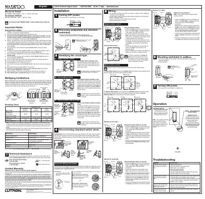
This manual provides the required safety notes, wiring diagrams, installation steps and troubleshooting procedures for the Lutron Maestro electronic switch (model MA/MSC‑S8AM) and its accessory switch (model MA/MSC‑AS). It also includes warranty information and technical support contacts.
The document covers single‑location, multi‑location and 4‑way configurations, wiring requirements such as the need for a neutral wire on the electronic switch, maximum load limits, and recommended wallbox depth. It explains how to connect ground, neutral, live, brass, black and blue terminals, and provides a derating chart for different load conditions.
| Electronic Switch voltage / frequency / current | 120 V ~ 60 Hz, 8 A max |
|---|---|
| Accessory Switch voltage / frequency / current | 120 V ~ 60 Hz, 8.3 A |
| Recommended minimum wallbox depth | 2.5 in (64 mm) |
| Operating temperature range | 32 °F (0 °C) to 104 °F (40 °C) |
Yes, the electronic switch (MA/MSC‑S8AM) requires a neutral wire for operation; if none is present, a licensed electrician must be consulted.
One electronic switch can be used with up to nine accessory switches (MA/MSC‑AS).
The electronic switch is rated for a maximum load of 8 A (950 W) when no side sections are removed, with lower limits when sides are removed.
No, the Maestro electronic switch is not compatible with standard 3‑way or 4‑way switches; only Maestro accessory switches may be used.